Hardware
The hardware is based upon an Arduino Due microcontroller, with a custom circuit board to interface to the various instruments.
The circuit board is designed in KiCad, source files are available under the hardware tree of the git repository. Gerber files suitable for production are also available in the gerber directory.
The device connects to the laser sync input, optical chopper wheel input and output sync, delay stage trigger and quadrature position inputs, and camera trigger output.
A combination of an inverting buffers and voltage divider networks convert the microcontroller’s 3.3 V levels to the 5 V levels expected by the instruments. A balanced line receiver is used to interface to the delay stage’s quadrature position inputs.
The physical connections to the Arduino Due I/O pins are:
Pin 2: Quadrature channel A (QA) in
Pin 3: Chopper sync out
Pin 4: Laser sync in (joined to pin 30)
Pin 5: Camera trigger out
Pin 10: (joined to pin 11)
Pin 11: (joined to pin 10)
Pin 13: Quadrature channel B (QB) in
Pin 30: Laser sync in (joined to pin 4)
Pin 6: Chopper sync in (any available pin, software defined)
Pin 8: Delay trig in (any available, software defined)
Extensive use of the Arduino Due’s timer/counter hardware is used, which mandates the purposes of some specific pins.
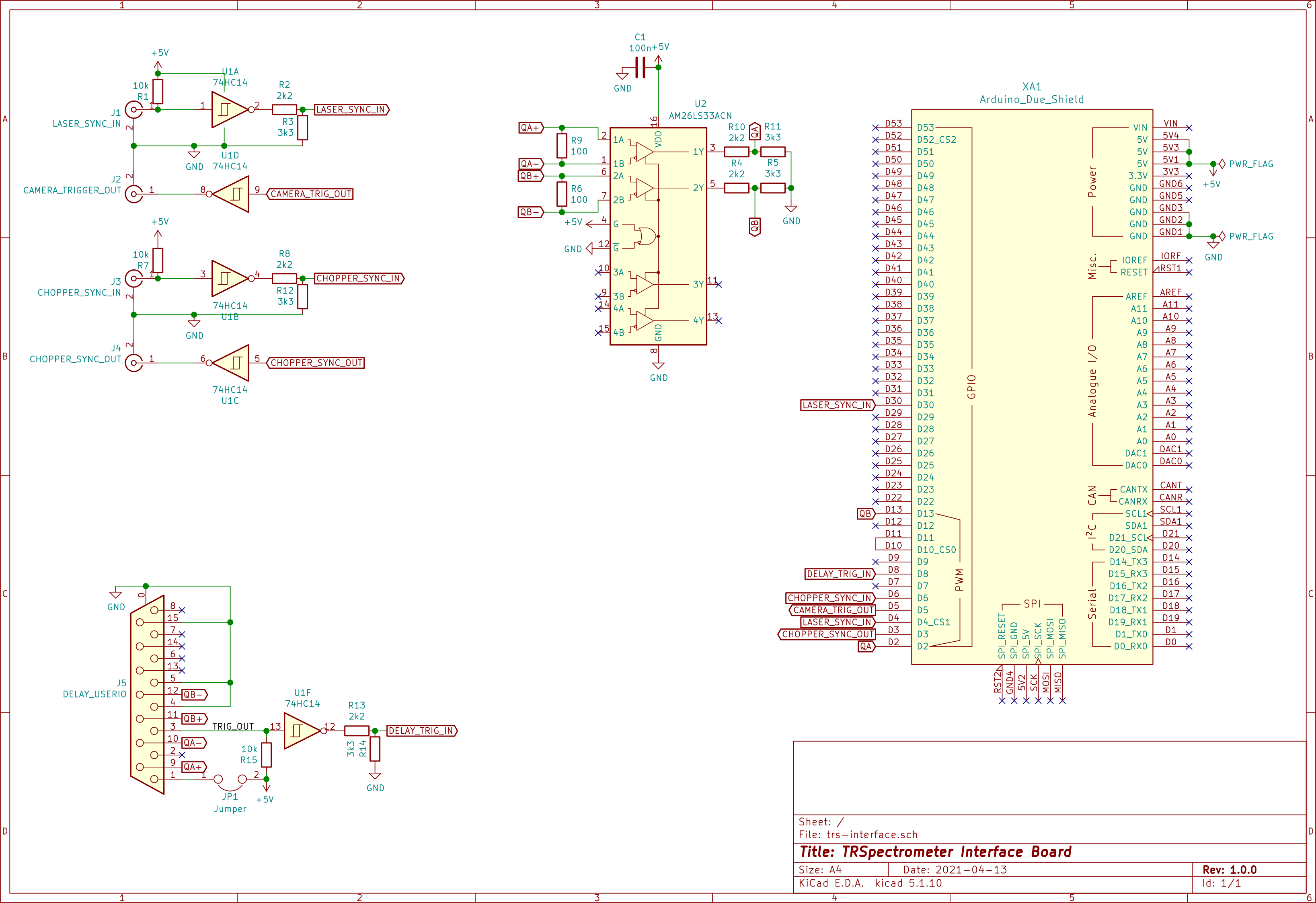
TRS-Interface circuit schematic.
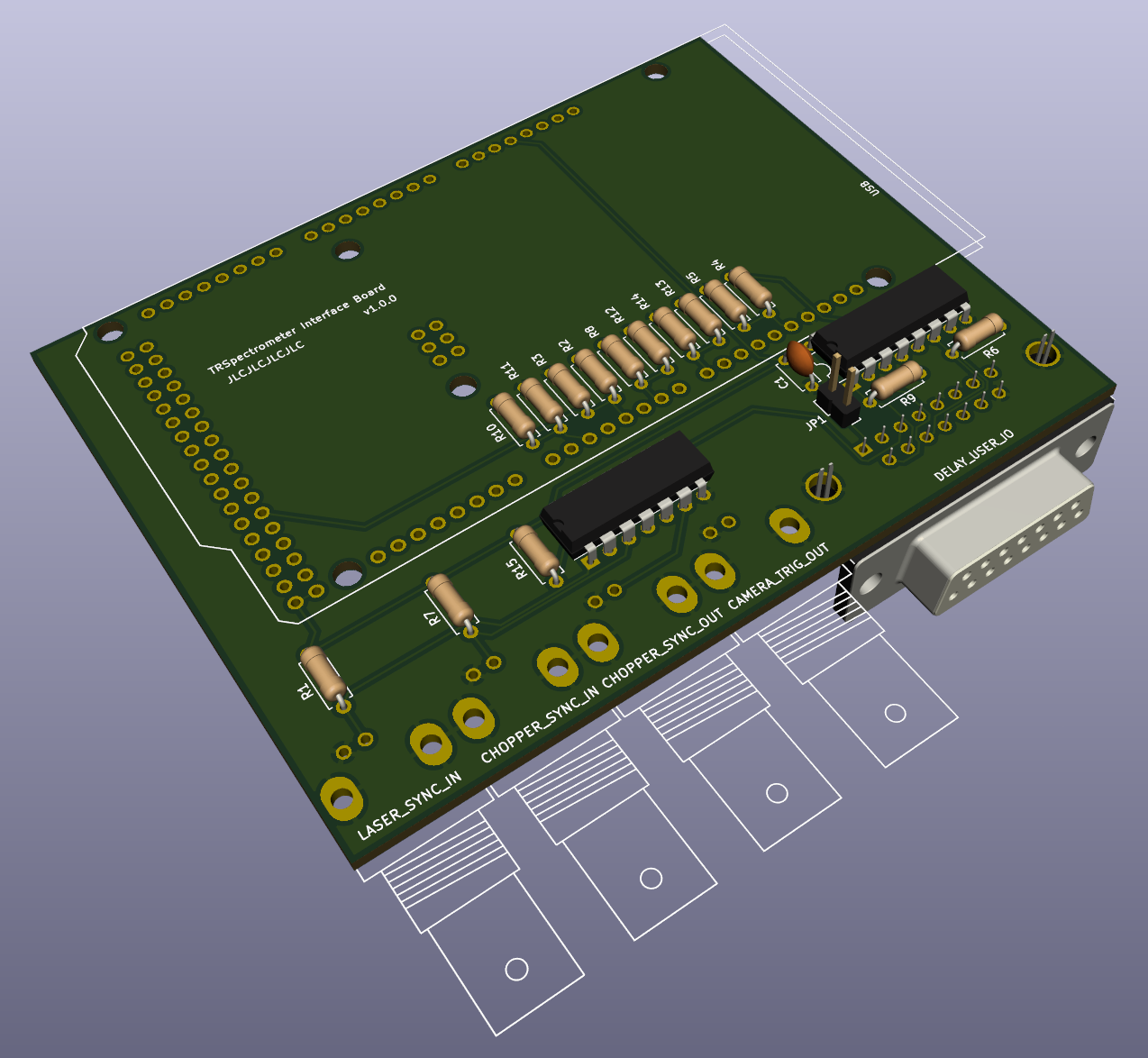
Render of the TRS-Interface circuit board.
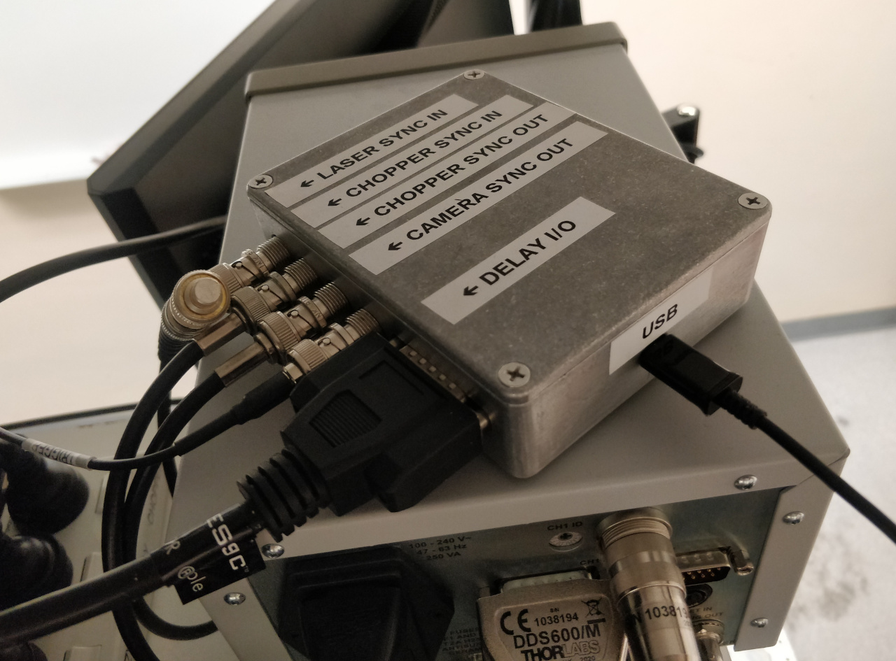
The interface boxed up, connected to the other equipment and in use. The instrument below it is a Thorlabs BB201 brushless DC motor controller used to control the delay stage.